LMU2630 Installation
Contents
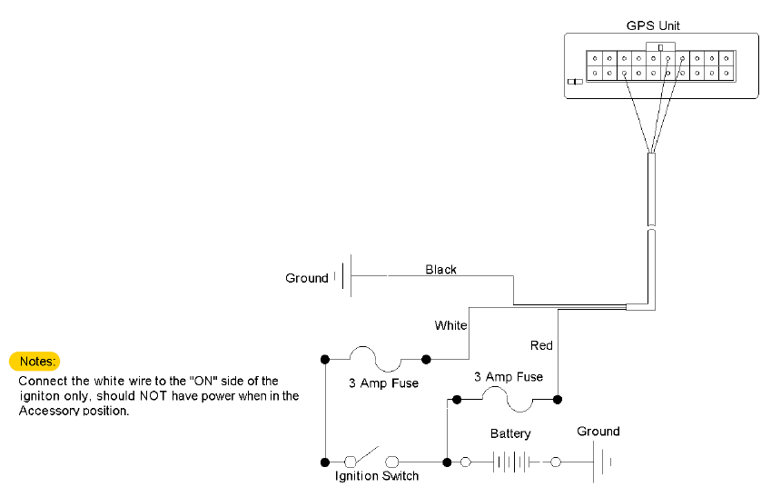
Vehicle Wiring Diagram
For CalAmp LMU2600 GPS units – Basic Install – Power Only
PLEASE READ THE NOTES BELOW – These instructions need to be followed correctly or the system will not function as designed.(If you are unsure how to install this system please hire a professional GPS installer to do this. An installer that is familiar with GPS installation will understand these instructions and will know the correct way to install the device. Davisware works with professional installers and will recommend one to you. Thanks) This is a general reference as to how the unit should be wired to allow for proper function of the software. The wiring can be routed in any manner that is safe and will provide the correct power and function to the unit.
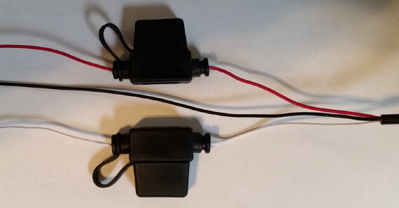
- It is recommended that all fuses be used as shown.
- Don’t push a test probe in the 20 pin connector, this will spread the connector and cause the wire harness to intermittantly connect to the unit. This will cause intermittant problems with function.
- All wire connections to the vehicle should be secured with solder or with a positive crimp on connector. Just wrapping the wires together is NOT ACCEPTABLE. This will cause intermittant functionality issues.
- Any questions, please contact Davis Business Solutions at 847-426-6000.
Unit Installation
The GPS should be mounted as high up under the dash as possible but keeping it away from metal surfaces and not in
an area where the unit will be over heated by the sun. The units should not be heated by the sun!!! This means it
should not be mounted on the dash and it should not be placed under the plastic dashboard. It also should not be
placed near the heat ducts in the vehicle.
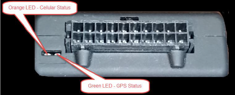
GPS Unit and LED Explanation below
Notes:
- GPS Staus (Green LED) should stay on solid at all times when the ignition is ON with the main power connected
and the GPS has a fix. This light will blink slow on power on and blink fast when it has a time sync. The normal
condition is when the light is on solid. On solid means the GPS has a GPS fix and is ready to track. This light will
be off when the unit is off and in sleep mode.
- Cell Signal (Orange LED) should stay on solid at all times when the ignition is ON with the main power connected
and the unit is registered on the cell service. This LED will blink slowly when searching for cell signal, it will blink
fast when a cell service is available and attempting to connect. The LED will also blink 4 times and pause when
the unit is registered but has not received an acknowledgement from the service. This light will be off when the
unit is off and in sleep mode.
Fuses on the Power cable
Recommended T-Tap Connector below.
- 3M 951 (TTAPR) Self-Stripping T-Tap Female Quick Slide Connector for 22 – 18 GA wire
- 3M 952 (TTAPB) Self-Stripping T-Taps Female Quick Slide Connector for 18 – 14 GA wire
- 3M 953 (TTAPY) Self-Stripping T-Tap Female Quick Slide Connector for 12 GA wire.
http://www.discountcarstereo.com/TTAPR.html
http://www.discountcarstereo.com/TTAPY.html
http://www.discountcarstereo.com/detail.aspx?ID=531
http://www.discountcarstereo.com/detail.aspx?ID=1452
http://www.discountcarstereo.com/detail.aspx?ID=721
Recommended Fuse Tap for use for the ignition power source below.
http://www1.cooperbussmann.com/pdf/214d9fff-7a93-4559-a7ff-089eeabdad20.pdf


